Electronic Clock I - Getting Started
This is a new series in which I will describe all the steps I went through while creating an electronic clock. Make sure you’re subscribed to the RSS feed so that you don’t miss out on anything!
Getting Started
An electronic clock is a good project for intermediate to advanced electronic hobbyists, which is why I decided to build one.
The first task is enumerating the requirements of the clock. A humble requirement list looks like this:
- Clock should run on a few AA cells
- It should have a 24 hour display
- It should display seconds, minutes and hours
- It should have two LED’s each to separate the hours, minutes and seconds
- It should be moderately compact
- It should be challenging to engineer and design
The second task is deciding what components will form the base of the clock (akin to choosing a language or a technology stack for developing an application). For a clock, a few options are available:
- Use a microcontroller:
- Interface a DS1307 clock module with the microcontroller using SPI, or
- Write your own code for a real-time clock in the microcontroller and use an external clock crystal (already done this here)
- Use CMOS/TTL Logic IC’s
I decided to go with the second option as I had already written code for a microcontroller clock and gone halfway through the implementation when I realized that it was too easy and did not provide a challenge. If you are a beginner, you should take the microcontroller route, as in case of bugs, they are easily rectifiable via your code, whereas debugging a hardware circuit (especially a large CMOS/TTL one) is decently hard for beginners.
Within a few minutes, I drew a basic block diagram for the main components in the circuit.
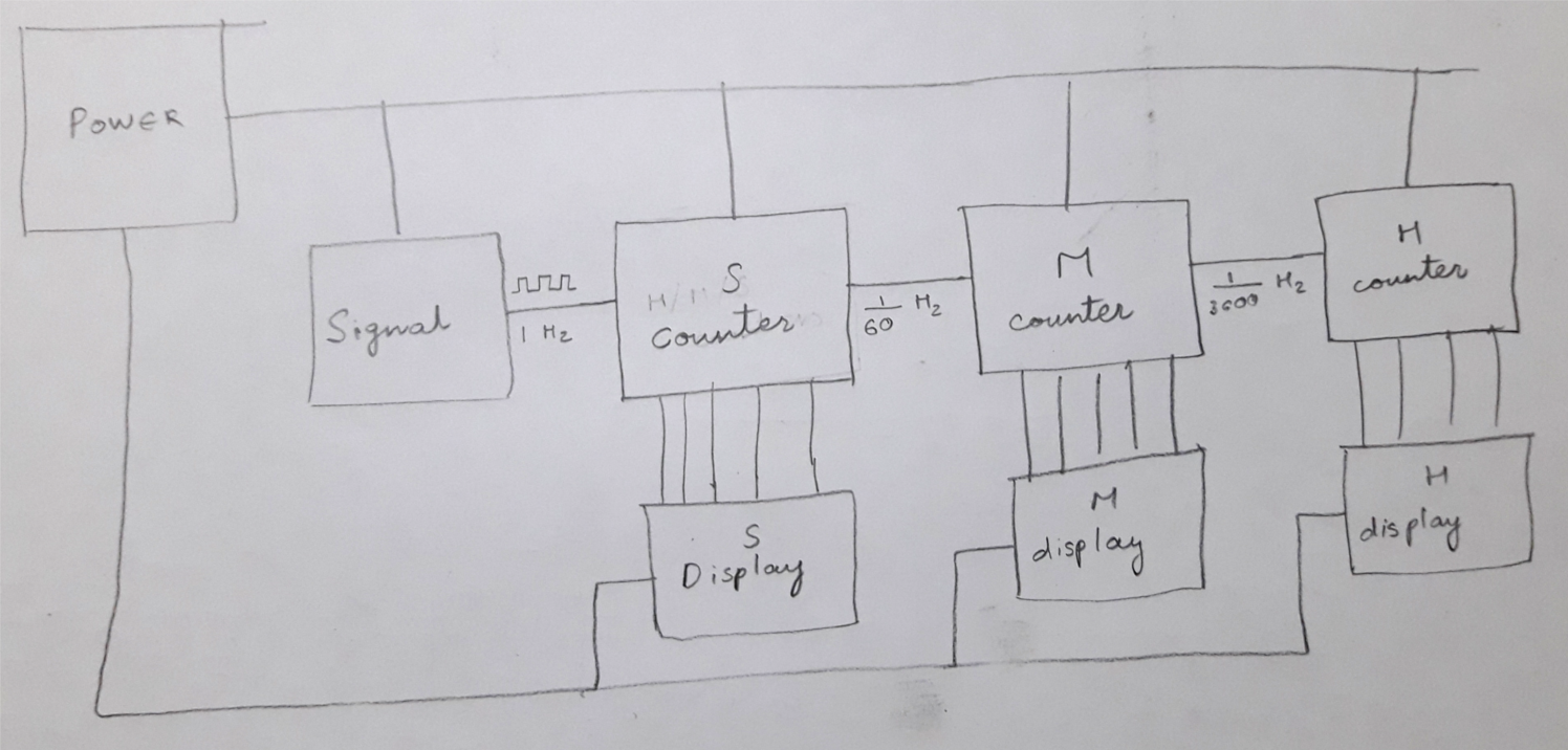
The circuit mainly consists of a 1Hz signal generator, a few counters/dividers and the display logic.
In the next segment, I’m going to build the signal generator and produce an accurate 2Hz signal that can be used by the other counters.
- Deb