Electronic Clock II - Generating the Clock Signal pt.1
In the previous installment of this series, I spoke about the requirements and the architecture of the clock. In this installment, I’m going to engineer the clock signal generator, the most crucial part of our clock
Importance of the Signal in a clock
Every clock is only as accurate as it’s signal. An atomic clock uses radiations emitted by cesium-133 as it’s signal, a quartz clock uses a 32768 Hz quartz crystal as it’s signal whereas a mechanical clock uses an Escapement powered by a hairspring (in wristwatches) or by a pendulum (in clocks). The signal has a cascading effect on the accuracy of a clock - even a 0.1% divergence in the period of the second hand causes a clock to lose or gain 86.4 seconds a day, or in larger terms, lose or gain almost half a day in a year!
Make an accurate electronic signal
Our clock (like most other clocks) is going to use a quartz crystal as it’s main signal. An RC or LC oscillator cannot be an accurate signal as the frequency will change with changes in temperature. Also, tuning an RC/LC oscillator to an exact frequency requires a ton of precision - the frequency has to be within a standard deviation of ±0.01%
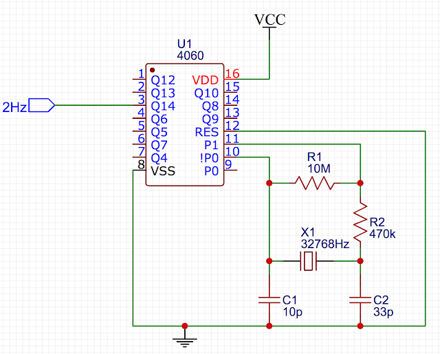
The signal generated by this crystal has a frequency of 32768 Hz, which isn’t very useful to us. In order to use it to drive the seconds counter, we must scale it down to 1 Hz (1 pulse per second). In order to do this, I will use a HEF4060, which is a 14 bit binary ripple counter.
The HEF4060 has the capacity to give us a minimum frequency of 32768/214 = 2 Hz. This will later be scaled down using a flip-flop to give us a frequency of 1 Hz. The circuit for this looks like the following:
After testing the above circuit on a breadboard, pin 7 (Q4) gave the following results on an oscilloscope:
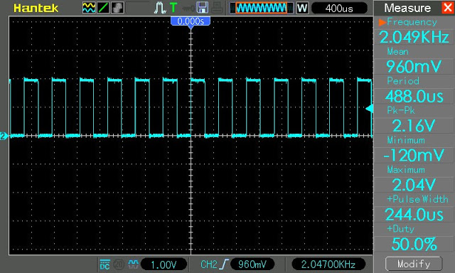
These results were expected as 32768/16 gives us 2048, which is approximately 2.049 kHz. the extra 1 Hz is probably a result of breadboard capacitance, which should go away once the circuit is soldered on a PCB.
In the next installment, I will use a flip flop to halve the 2Hz signal to give us a resultant signal of 1Hz, which can be used to drive the seconds counter.
- Deb