Icosahedron Resistor Network
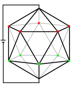
Consider the icosahedral resistance network shown in the following figure. Each edge is made of a rod of resistance $r$. Select the option(s) that is(are) correct:
A) The resistance between points A and B is $\frac{r}{2}$
B) The resistance between points A and B is $\frac{r}{3}$
C) The resistance between any two adjacent vertices is $\frac{11r}{30}$
D) The resistance between any two adjacent vertices is $\frac{11r}{20}$
This question looks really tricky. This is a variation of the problem of finding the resistance of a wire cube. This can be solved in a similar way, using symmetry and equipotential reduction.
Let’s start off by finding the resistance between A and B, since this is easier than finding the resistance between adjacent vertices. On connecting a battery, the points marked in the same colour will be at the same potential.
You can clearly see the symmetry now. If we connect all the points with the same potential, we end up with the following resistor network (each resistance is $r$).
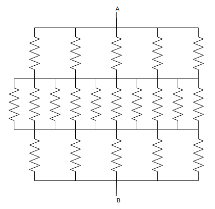
This is simple to solve. It’s resistance is $$R_{AB} = \frac r5 + \frac r{10} + \frac r5 = \boxed{\frac r2}$$ which corresponds to option (A).
Solving the network between adjacent vertices is a lot trickier. The first trick is to pick a pair of vertices from which symmetry is easily identifiable. If I connect my battery as shown in the following figure, it is easy to identify which points are equipotential and how the currents are flowing.
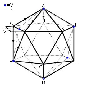
The dotted line shows the plane of symmetry of this icosahedron perpendicular to $CD$ whereas the blue dots show equipotential nodes. We can see that no current flows through $R_{AJ}$ and $R_{EB}$ since the ends are at the same potential. Also, at all equipotential points, no mixing of currents occurs. This means that $I_{AC} = I_{AD}$ and $I_{CE} = I_{ED}$, along with a few others. Performing some modifications on this circuit in line with the above observations reduces the complexity quite drastically as shown below:
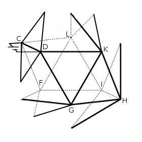
Simplifying these resistors, we obtain a cubical network with a resistor across two opposite face diagonals
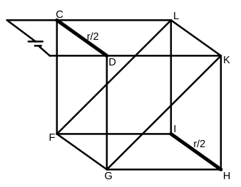
It is easy to see that $V_F = V_L$ and $V_G = V_K$. Connecting these two points and getting rid of the resistances $R_{GK}$ and $R_{LF}$, we get the following resistor network:
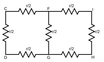
It is now simple to calculate the resistance across CD by using the formulae for resistors in parallel and series.
$$\begin{gather} \frac 1 {R_{FG}} = \frac 2 r + \frac 2 {3r} \\ R_{FG} = \frac{3r}{8} \\ \frac{1}{R_{CD}} = \frac{8}{11r} + \frac{2}{r} \\ \boxed{R_{CD} = \frac{11r}{30}} \end{gather}$$
Which corresponds to option (C)
A good problem that I came up with on my own; the next step is to do the same for a dodecahedric resistor network. Stay tuned for that :)